Aircraft Equations of Motiondraft
Introduction
The following definitions will be revision, but a thorough understanding of them is imperative for the remainder of this course.
Newton’s laws of motion
In this course we utilise Newtonian Mechanics - Newton’s laws should be familiar, and you should be able to recite them:
- An object remains at rest or in a state of uniform motion unless acted on by an external, unbalanced force.
- Net force acting on rigid body is equal to its absolute momentum flux, or .
- Every action force has a reaction force that is equal in magnitude, and opposite in direction.
Newton’s second law will be used in this section to derive the full six degree of freedom (6DoF) equations of motion for unconstrained aircraft flight. Before diving into the derivation, further definitions are required:
- Most of the quantities used are easiest to define in different axes systems
- A thorough understanding of relative motion will need to be employed
Reference Frames and Aircraft Axis Systems
All motion is relative - there is no luminiferous aether1, and there is no universal ‘grid system’ in which we can define position or motion. In the absence of this, we define different axes systems depending on what helps to simplify the mathematics that we need to use - it is easier to define forces in an axis system where those forces are aligned with the reference system.
Newton’s laws are only valid in an inertial reference frame - one that is not moving. We use the Earth as our inertial reference frame - this is not actually the case as it is obviously moving, but for flight mechanics purposes, we rely on the fact that the rotation of the Earth is slow compared to aircraft motions.
A note on vector notation
To differentiate vector quantities from scalar quantities, several conventions are commonplace. If are vector components, the vector may be defined using
-
Boldface
-
Arrow
-
Underline
I tend to use in typeset documents as it causes the least conflicts when using LaTeX. When writing on the board, I tend to use notation as it is easier - but sometimes I’ll draw an arrow if I’m feeling adventurous2. I don’t mind which you use, as long as you are consistent within a single derivation. Just be aware that things change between sources.
Earth Axes
We utilise the Earth axis system, see Figure Introduction, because, for our purposes, it is an inertial reference frame - so we require this in order to utilise Newton’s second law. We make some simplifications, and impose the following:
-
Assume the Earth is a flat plane 3
-
NED (North, East Down) =
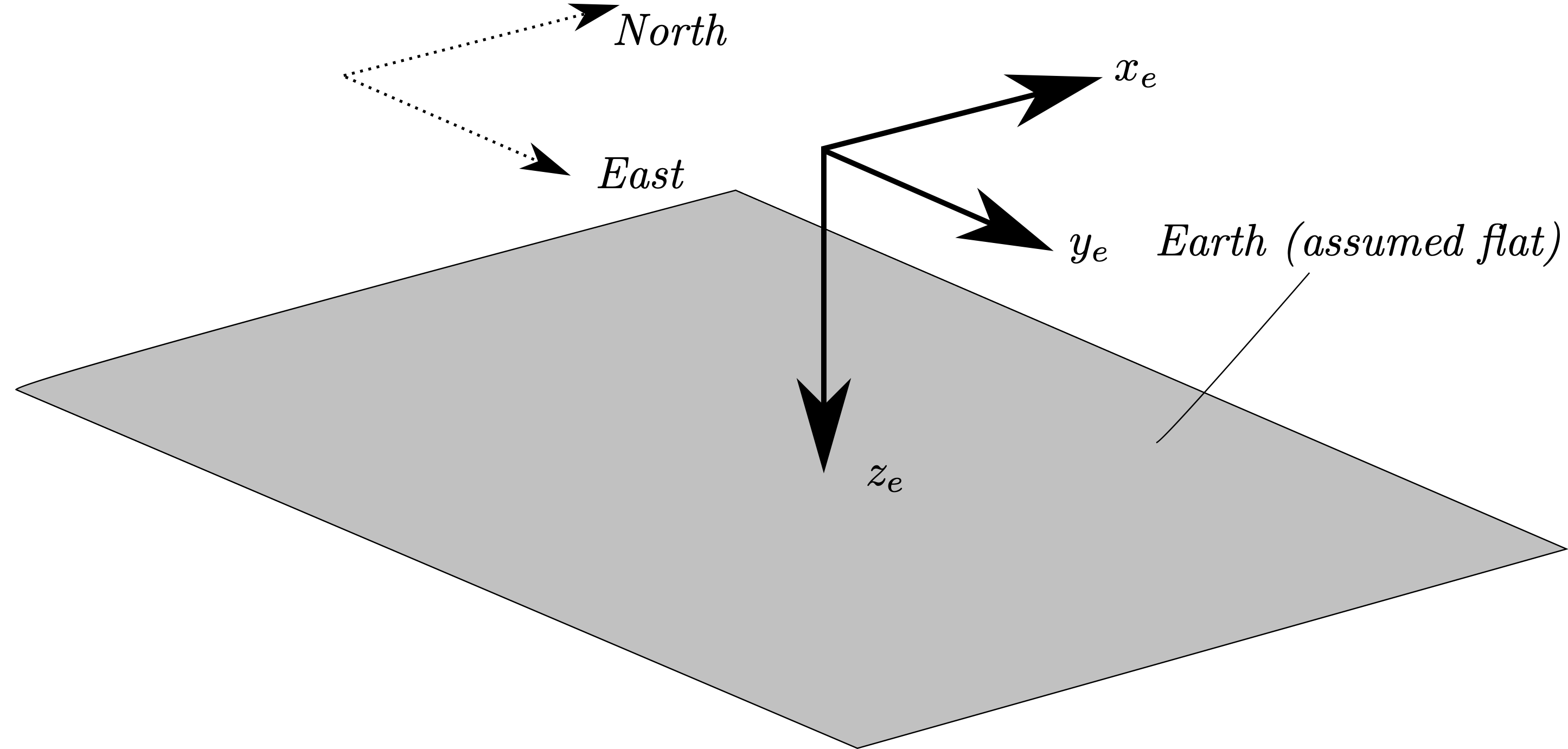
Earth Axes
Aircraft Body Axes
We also require a frame of reference that is fixed to the aircraft because:
-
That is the frame of reference in which the pilot sits, so we require one to determine forces on them
-
Moments/products inertia, and centre of gravity position are easily defined in an axis system fixed to the aircraft
This axis system is usually defined with its origin at the aircraft centre of gravity.\
is defined positive forward, and may be defined along the propeller rotation axis for a single-engine propeller-driven aircraft, along the floor for a large transport aircraft, or along the wing root chord line.
is defined along the starboard axis along a plane equidistant vertically from both wings at each spanwise location ( does not not travel along a wing dihedral angle).
is defined down, normal to the plane defined by the , intersection.
These have already been introduced in the previous module.
We can normally define thrust in aircraft body axes, and we may also define aerodynamic forces in body axes (as normal and axial force), but it is more convenient to define aerodynamic in stability axes as lift and drag.
Stability Axes
Aircraft, in general, are usually flown at some angle of attack, - which means that the incident freestream velocity is not aligned with the aircraft body axes. Lift and drag are defined parallel to, and normal to the incident flow vector, so we require an axes set called stability axes - .
We rotate the aircraft body axes through , around - thus .
The planes of body and stability axes intersect along the shared axis.
The planes of body are co-planar, but rotated about .
It is important to note that this treatment neglects sideslip - so we are treating as the projection of the relative wind into the aircraft body plane.
Aircraft data is usually defined in the stability axes system - it is important, however, to have an appreciation of wind axes.
Wind Axes
Stability axes are defined from the projection of freestream into the plane. That is, disregarding sideslip.
Wind axes take account of this, and are aligned with defined along the actual freestream.
In general, however, aircraft coefficients will be defined in stability axes - but you should have an appreciation of this axis set.
Defining quantities in different axes sets
The axes systems that used in this course have been described - as mentioned earlier, it is easier to define certain quantities in one axis system over another:
Gravitational Force - Weight
The aircraft weight vector is, by definition, aligned with the Earth Z () axis as it is oriented towards the centre of the Earth. That is:
Displacements
For positioning purposes, the aircraft location must be defined in earth axes.
Propulsive Forces
Aircraft thrust is generally aligned along the aircraft -axis , and is thus best defined in body axes:
For this course we will disregard effects such as thrust axis misalignment or thrust vectoring, so this simplifies to
Aerodynamic Force
The aerodynamic forces of lift, , and drag, , are, by definition, defined normal to and parallel to the incident flow vector, . It is most useful to use these force in stability axes:
Where the term is the side component of aerodynamic force due to sideslip.
Translations and Rotations
Aircraft velocity and accelerations are defined in body axes:
One must be careful with the equation above; in the case of zero angular motion, you may differentiate the absolute velocities to obtain the absolute acceleration , but for the case of non-zero angular velocity, these are not equivalent, . This will all make a lot more sense (hopefully) when you’re introduced to Coriolis theorem later, but the fact that we cannot get absolute accelerations so simply deserves a mention at this juncture.
Angular velocities of the aircraft, with respect to the inertial reference frame, are defined in body axes as roll, pitch, and yaw rates:
Note that if you see , , or in practice, they are defined as body angular rates, and are as measured in body axes.
Aircraft total forces and moments
We define the total external forces and moments on the aircraft in body axes
The requirement for axis conversion
Since it is desired to utilise Newtonian mechanics to define the motion of the aircraft, it is hence needed to be able to equate forces to the product of mass and accelerations (Newton’s second law).
So far, forces, displacements, and velocities are defined in all three axis systems - earth, body, and stability.
Relating stability and body axes is relatively simple since they are only rotated through a single angle, . Body and earth, by contrast, are oriented at an arbitrary angular displacement to each other.
The aircraft attitude defines the relationship between earth and body axes, and this hence allows conversion of quantities between the two different axes systems.
To define the aircraft attitude, there are different ways that can be chosen from mathematics:
-
Sequence of Rotations
-
Quaternion methods
-
Direction cosine matrix
In this course, we will use the sequence of rotations - yaw, pitch, roll. These need to be defined in that order.4
Footnotes
-
Read the ‘Michelson-Morley experiment’ if that means nothing to you ↩
-
I know, way to live dangerously. ↩
-
This doesn’t make you a flat earther, don’t worry. ↩
-
Well, you can define them in whatever order you want, but the resulting transformation matrix will be different, and hence incorrect - and the standard for aerospace is 1. yaw, 2. pitch, 3. roll. ↩