In deriving the equations of motion, we use Newton’s Second Law as the basis for equating force and the rate of change of both translational and angular momentum:
∑F=m⋅aabs
where aabs is the absolute acceleration that defined in an inertial reference frame. Body axes velocities and displacements may be converted to absolute quantities via the Euler angle translation, but accelerations may not be treated as such, owing to the relative motion of the body axes with respect to the earth axes. Stated another way, the body accelerations are not absolute:
∑Fx=m⋅U˙∑Fy=m⋅V˙∑Fz=m⋅W˙
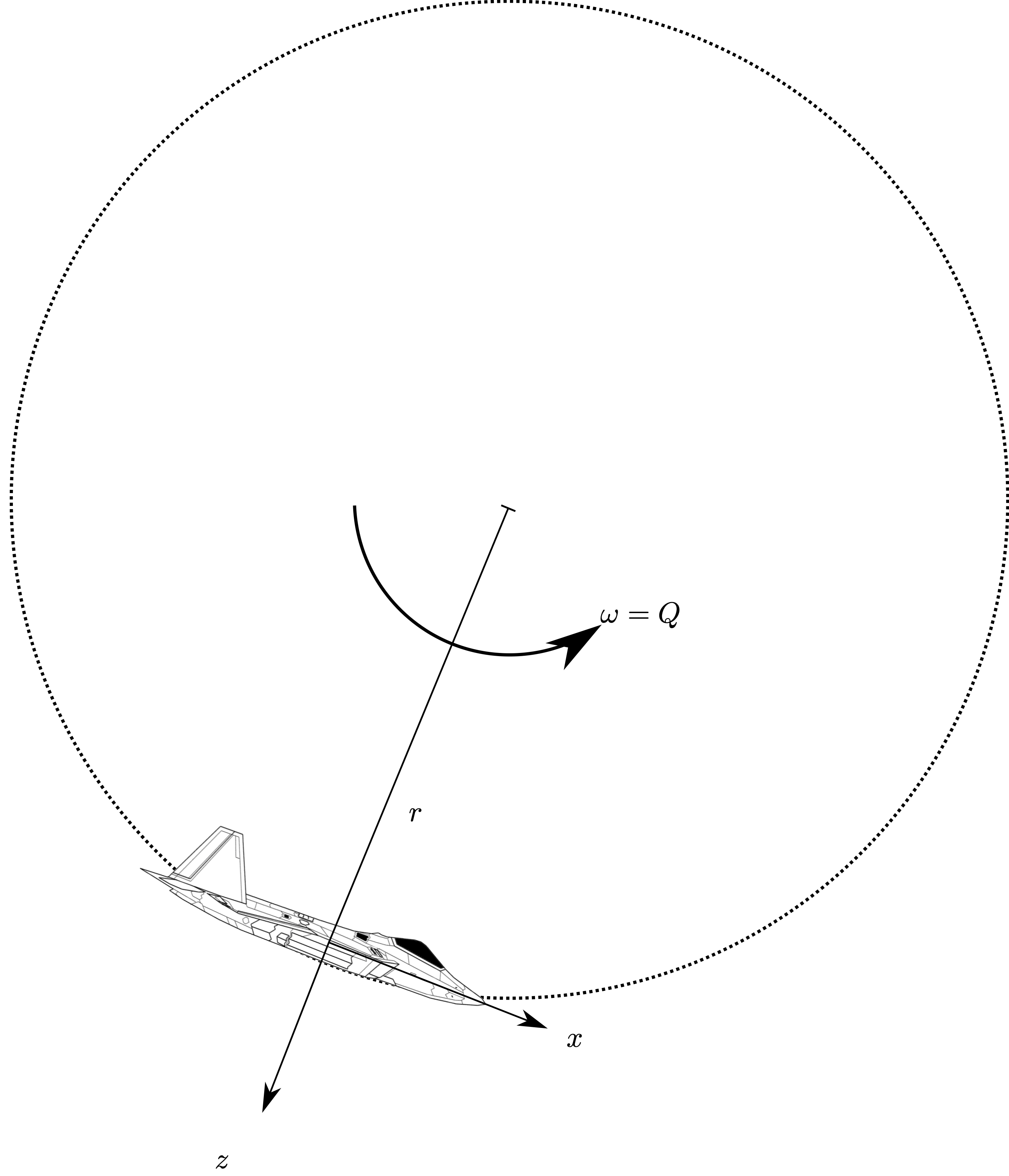
This may be demonstrated with a counterexample - an aircraft flying in a loop - see Figure Fig. 1.
Fig. 1:
Aircraft flying in a loop
From basic physics, we know that for steady motion in a circle of radius r with angular velocity Ω, the centripetal (centre seeking) acceleration is:
ac=r⋅ω2
and that the tangential velocity, which in this case is equal to the aircraft u velocity i
U⟹r=r⋅ω=ωU
which, if we substitute into our expression for centripetal acceleration and recognise that for this example, the angular rate ω is equal to the body rotation rate around the y axis:
ac=Q⋅U
which gives us an apparent acceleration along the body z axis due to angular rotation, which is to be added to the local acceleration:
az=W˙−QU=∑mFz
If we were to include terms because of all three body rates (you’d have to draw a similar example for a yaw rate - or wait until you’ve got the Coriolis identity), we would see that:
az=W˙−QU+PV
We can see that absolute acceleration is the sum of translational acceleration AND the vector product of angular and translational rates. Whenever we have rotation, we cannot simply treat absolute acceleration as the time derivative of velocities. In the following section, we’ll develop a methodology to treat this formally.
Relative Motion: General Form
The extra terms arise because the aircraft axes are moving with respect to earth axes; body axes are a non inertial reference frame and (for our purposes) earth axes are. You are probably able to intuit some of these terms - such as the centrifugal force that is perceived in a rotating reference frame due to angular translation. We’ll develop a mathematical formulation to show the following
where (8) and (2) are the first and second order Coriolis identities. ‡ is a vector quantity relating to translational motion. So, to yield absolute acceleration the absolute velocity can be used as ‡ in (8) or the absolute position can be used in (2). ()abs refers to absolute quantities, which is what we need for Newton’s second law, whilst dtd()Oxyz refers to differentiation in a non-inertial reference frame.
Equations (8) and (2) tend just be given to the engineering student without a derivation, and I hate that sort of instruction since it doesn’t help learning or understanding, just parroting.
How will (8) and (2) be determined? Well we know that the effects are related to rotation of a non-inertial reference frame within an inertial one, and some rotation. So that looks like a good place to start.
General position and velocity vectors in unit vector form
The general expressions for position and velocity are, as defined in a non-inertial reference frame (e.g., aircraft body axes)
r=xyz(3)
V=UVW(4)
The derivation can be performed using either. Taking Equation (3) and writing in unit vector form:
r=x^+y^+zk^
and the first derivative can then be written, using the product rule - noting that ()˙ denote absolute derivative.
r˙=x˙^+y˙^+z˙k^x^˙+y^˙+zk^˙(5)
The terms x˙,y˙,z˙ are easy to intuit their meaning - these refer to any change in the vector in the non-inertial reference frame. The second set of terms ^˙,^˙,k^˙ are slightly less instructive. These refer to an apparent derivative that arises due to angular motion; if the original vector is r, then these are an apparent velocity. If the vector is V then these are an apparent acceleration.
Since these are caused by angular rates ω=[P,Q,R]T, the effect of each of these rates can be explored on the unit vectors in time Δt - the limit of this change as Δt→0 will give expressions for ^˙,^˙,k^˙.
Since P, Q, and R are all defined as rotations about body axes they can be explored independently as three Euler rotations - sequence is irrelevant here.
If the unit vectors can be written as
I=[^,^,k^]T
then
I˙=Δt→0limΔtΔI
and the total change to I is the sum of the changes due to the three angular rates
ΔI=ΔIP+ΔIQ+ΔIR(6)
and all of the RHS components in (6) can be determined from Euler transforms. Consider each rotation as a movement from I to I′. The diagrams three Euler transforms are given below:
ΔIP - change to unit vectors due to body roll, P
The angular displacement during time Δt due to body roll rate is PΔt:
the first order Coriolis identity - and can be used to yield absolute acceleration from a velocity vector, or absolute velocities from a position vector.
Sometimes the second order Coriolis identity is required, as we’ll see - and there are two ways of yielding it:
Differentiate Equation (5) again and yield the following, Eqn (9).Then get the I^¨ terms by substituting I^˙ into Eqn (8), then populating Eqn (9) turning into matrix form
The second way is a little easier - you can basically substitute Eqn (8) into itself.
In the general form of relative motion derived in the preceding section. We can use a relative motion approach to derive expressions for the absolute aircraft velocities based on data measured at a location away from the aircraft centre of gravity.
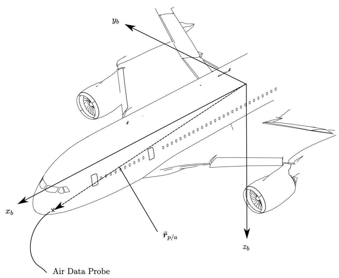
Fig. 5:
Air data probe in aircraft axes
Consider an aircraft with a co-ordinate system located at its centre of mass, and an air data probe located on a the nose at location rp/a=[xp,yp,zp]bT, measured in body axes, Figure Absolute Acceleration. Since this the location in body axes, the position vector is the relative position of the probe to aircraft axes.
That is, if the aircraft position is ra in the absolute reference frame, the the absolute position of the probe is
rp=ra+rp/a
The air data probe measures angle of attack, sideslip, and total velocity - all at the location of the probe. From what we have learned about relative motion, we know that these will not be the same as those for the aircraft centre of mass, so we need a means to convert these measured values back to aircraft absolute velocities - for use in Flight Mechanics. We denote the quantities measured at the probe as αp,βp,Vfp, and what we desire is U,V,W,Vf,α,β.
Expressions are required for the absolute velocity as measured at the probe, so we start with the vector expression for the absolute position of the probe (its position in earth axes).
rp=ra+rp/a
the absolute velocity is the time derivative of this
r˙p=r˙a+r˙p/a
the first term above is simply the aircraft absolute velocity, Va=[u,v,w]T, and the second term we get from the Coriolis identity
which gives us the aircraft absolute velocity as a function of those measured at the probe, its position, and the aircraft angular rate (which would be measured at a rate gyroscope in the aircraft). However, we do not have Up,Vp,Wp, we have the local aerodynamic angles and the total velocity, so we need to develop expressions for them using the definition of total velocity and the aerodynamic angles
and the aircraft angle of attack may be developed from the standard aerodynamic angle definitions.
The terms r˙p/a=[x˙p,y˙p,z˙p]T represent a velocity due to any change in position of the probe in aircraft axes - that is due to aircraft flexibility.